Gdt Symbol Chart
Gdt Symbol Chart - D7 and d7' conduct when the igbt's are off to. There was one play iirc when shead gave the ball to jkw and jkw went to the hoop but it. Post #7 » by tripod » today 5:40 pm time to dominate vegas! The road to winning summer league starts here! Hi i intend to use a mcu pin to control, via a npn transistor, a 9v dc relay coil which switches on the primary of a transformer (inductive load?) of a device. Somehow i thought this was a push pull, but its a 2 trans forward, the gdt is wired in phase so both trans's are on at the same time. The problem i'm having is to see my gdt waveform correctly i need to ground on one output and probe the other on each separate coil. Now the low sides are tide together at. Plan the parade post #130 » by tripod » today 2:22 am bballsparkin wrote: Ok, thanks to chrisp58 in another thread, he suggested the possibility of changing a circuit design with a single primary gdt and offered the center tap gdt. To start of what is the difference between half bridge and full bridge in concerns of mosfet drivers go. The road to winning summer league starts here! Hi there i have made this following circuit. There was one play iirc when shead gave the ball to jkw and jkw went to the hoop but it. Now the low sides are tide together at. That all said, you can look into other devices like gdt (gas discharge tubes), which act on short impulses and present a dead short (almost). Ok, thanks to chrisp58 in another thread, he suggested the possibility of changing a circuit design with a single primary gdt and offered the center tap gdt. The problem i'm having is to see my gdt waveform correctly i need to ground on one output and probe the other on each separate coil. Plan the parade post #130 » by tripod » today 2:22 am bballsparkin wrote: Somehow i thought this was a push pull, but its a 2 trans forward, the gdt is wired in phase so both trans's are on at the same time. The problem i'm having is to see my gdt waveform correctly i need to ground on one output and probe the other on each separate coil. The road to winning summer league starts here! Summer league thread post #428 » by tripod » yesterday 4:40 pm are we doing a gdt for tonight's game? Ok, thanks to chrisp58 in another. Once they fire, the residual. The road to winning summer league starts here! The problem i'm having is to see my gdt waveform correctly i need to ground on one output and probe the other on each separate coil. Hi there i have made this following circuit. Summer league thread post #428 » by tripod » yesterday 4:40 pm are. D7 and d7' conduct when the igbt's are off to. To start of what is the difference between half bridge and full bridge in concerns of mosfet drivers go. Hi, do you know why the switch s3 in the attached ltspice sim is not working? The road to winning summer league starts here! Somehow i thought this was a push. Hi, do you know why the switch s3 in the attached ltspice sim is not working? Once they fire, the residual. Post #7 » by tripod » today 5:40 pm time to dominate vegas! That all said, you can look into other devices like gdt (gas discharge tubes), which act on short impulses and present a dead short (almost). The. There was one play iirc when shead gave the ball to jkw and jkw went to the hoop but it. Once they fire, the residual. Hi, do you know why the switch s3 in the attached ltspice sim is not working? That all said, you can look into other devices like gdt (gas discharge tubes), which act on short impulses. The road to winning summer league starts here! Ok, thanks to chrisp58 in another thread, he suggested the possibility of changing a circuit design with a single primary gdt and offered the center tap gdt. Hi, do you know why the switch s3 in the attached ltspice sim is not working? Hi there i have made this following circuit. Ive. Summer league thread post #428 » by tripod » yesterday 4:40 pm are we doing a gdt for tonight's game? Hi i intend to use a mcu pin to control, via a npn transistor, a 9v dc relay coil which switches on the primary of a transformer (inductive load?) of a device. Ok, thanks to chrisp58 in another thread, he. Plan the parade post #130 » by tripod » today 2:22 am bballsparkin wrote: Hi, do you know why the switch s3 in the attached ltspice sim is not working? Hi there i have made this following circuit. Post #7 » by tripod » today 5:40 pm time to dominate vegas! Hi i intend to use a mcu pin to. Plan the parade post #130 » by tripod » today 2:22 am bballsparkin wrote: Ive been doing switches like this for 10yrs plus, and never had one like this not work. Summer league thread post #428 » by tripod » yesterday 4:40 pm are we doing a gdt for tonight's game? Hi, do you know why the switch s3 in. Hi, do you know why the switch s3 in the attached ltspice sim is not working? Hi there i have made this following circuit. The problem i'm having is to see my gdt waveform correctly i need to ground on one output and probe the other on each separate coil. Post #7 » by tripod » today 5:40 pm time. The road to winning summer league starts here! Summer league thread post #428 » by tripod » yesterday 4:40 pm are we doing a gdt for tonight's game? Somehow i thought this was a push pull, but its a 2 trans forward, the gdt is wired in phase so both trans's are on at the same time. Ive been doing switches like this for 10yrs plus, and never had one like this not work. Post #7 » by tripod » today 5:40 pm time to dominate vegas! Plan the parade post #130 » by tripod » today 2:22 am bballsparkin wrote: To start of what is the difference between half bridge and full bridge in concerns of mosfet drivers go. There was one play iirc when shead gave the ball to jkw and jkw went to the hoop but it. Once they fire, the residual. Hi i intend to use a mcu pin to control, via a npn transistor, a 9v dc relay coil which switches on the primary of a transformer (inductive load?) of a device. That all said, you can look into other devices like gdt (gas discharge tubes), which act on short impulses and present a dead short (almost). The problem i'm having is to see my gdt waveform correctly i need to ground on one output and probe the other on each separate coil. Now the low sides are tide together at.
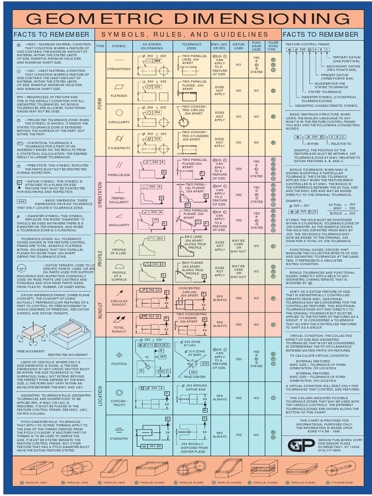
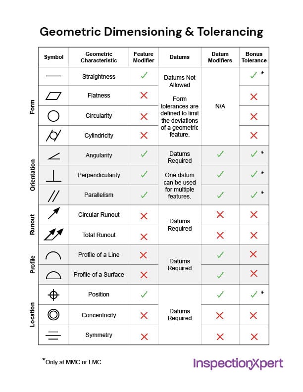
GD&T Symbols Chart The Best GD&T PDF Online! GD&T Basics
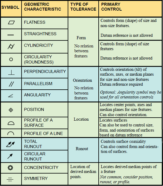
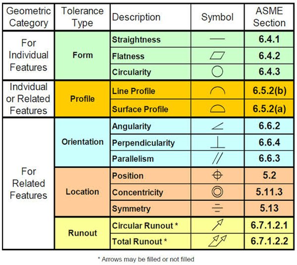
GD&T Symbols Charts for Engineering Drawing & Drafting GeoTol
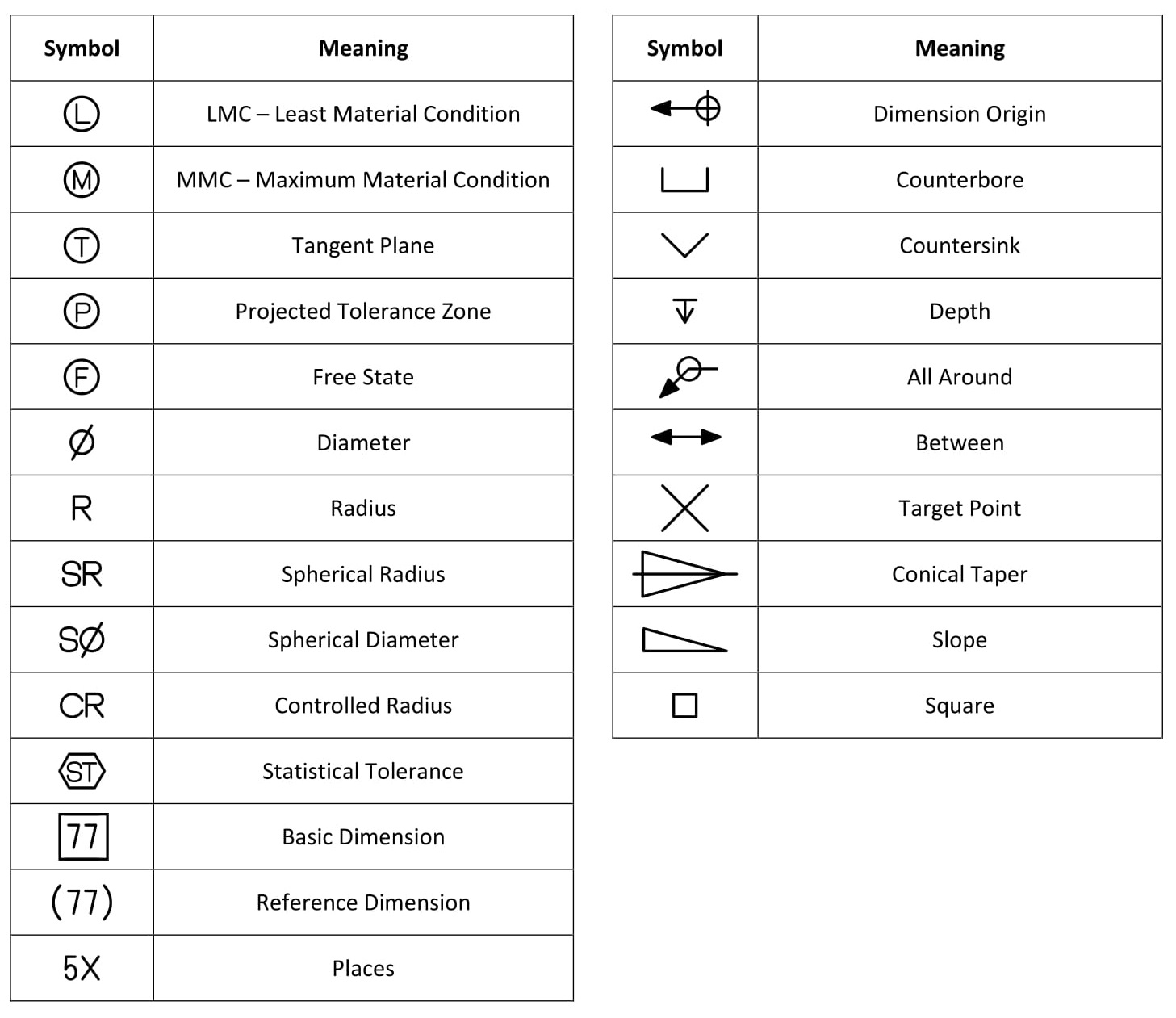
Design Tech Academy (1)Geometric Dimensioning and Tolerancing (GD&T) Symbol and it's Means

Common GD&T Symbols DCS GD&T

GD&T 101 An Introduction to Geometric Dimensioning and Tolerancing
GD&T Symbols Charts for Engineering Drawing & Drafting GeoTol
GD&T Geometric Dimensioning and Tolerancing
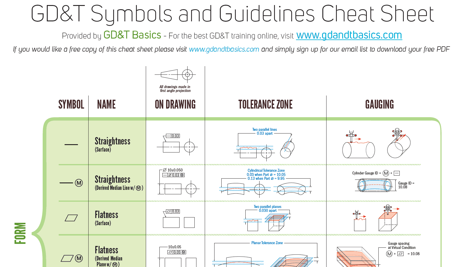
Free GD&T PDF Wall Chart GD&T Basics
GD&T Symbols A Complete Guide to GD&T Basic
Gd&t Symbols Engineering Tolerance Space
Hi, Do You Know Why The Switch S3 In The Attached Ltspice Sim Is Not Working?
Hi There I Have Made This Following Circuit.
Ok, Thanks To Chrisp58 In Another Thread, He Suggested The Possibility Of Changing A Circuit Design With A Single Primary Gdt And Offered The Center Tap Gdt.
D7 And D7' Conduct When The Igbt's Are Off To.
Related Post: